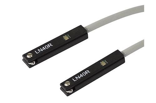

Specifications
| Wiring method | LN40R : 2 wire, LN40R-N, LN40R-P : 3 wire |
|---|---|
| Switching logic | LN40R : N.O., LN40R-N, LN40R-P : Without contact,N.O. |
| Switch type | LN40R : Reed switch, LN40R-N : NPN current sinking, LN40R-P : PNP current sourcing |
| Operating voltage | LN40R : 5~120V DC/AC, LN40R-N, LN40R-P : 5~30V DC |
| Switching current | LN40R : 100mA max. LN40R-N, LN40R-P : 200mA max. |
| Switching rating | LN40R : 10W max. (※1) LN40R-N, LN40R-P : 3W max. |
| Current consumption | LN40R-N, LN40R-P: OFF:7mA(24V)/ ON:17mA(24V) max. |
| Voltage drop | LN40R : 2.5V max. , LN40R-N, LN40R-P : 1.5V@100mA max. |
| Indicat | LN40R, LN40R-N : Red LED, LN040R-P : Yellow LED |
| Cable | LN40R : φ3.0,2C,PVC ; LN40R-N, LN40R-P : φ3.0,3C,PVC |
| Temperature range | -10℃~+70℃ ( No freezing ) |
| Enclosure classification | IEC 60529 IP67 |
| Protection circuit | LN40R : 1, LN40R-N, LN40R-P : 3,4 (※2) |
| Remark | ※1 : Warning: Never exceed rating ( watt = voltage × amperage ). Permanent damage to sensor will occur. ※2 : 1=None / 2=Short-circuit / 3=Power source reverse polarity / 4=Surge suppression. |

Online Inquiry